


Belgium
Shopping pages


Max7219 Maxim integrated circuit for 7-segment displays
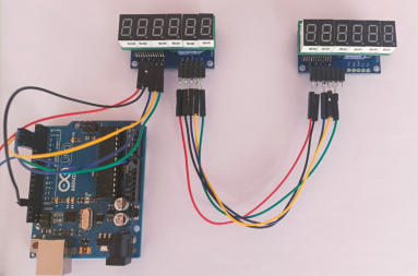
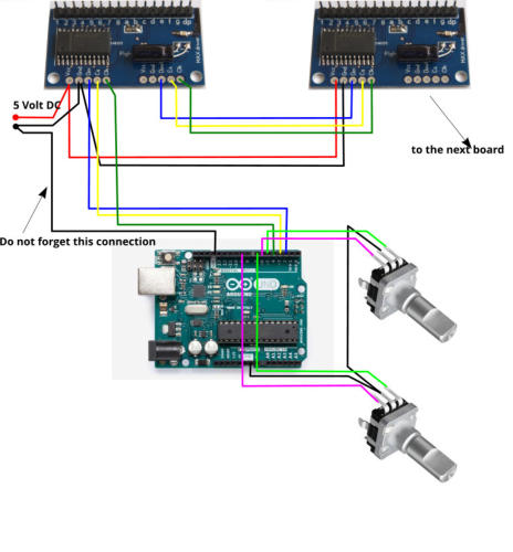
Below is the schematic diagram as an example of how to connect things. Used are 2 Max drivers,
1 Arduino UNO, 2 encoders and 2 times 6 digit boards.
This example is a full set to construct a COM radio and display the frequencies or change them.
It is based on X Plane and Mobiflight. If you are using MSFS or other simulators, you just have to
change the simulator in Mobiflight and the link to the COM radio.
They can be pre-ordered, so you can enjoy the first batch. Also, available are connection cables between
different boards. Contact if you want to reserve some.

This configuration file is an example how to display
the frequencies of a COM radio, both the actual and
standby frequency.
First tests with the new boards
Download a test script with Air Manager
The script is made for a test with 4 drivers
connected with our cables.